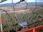
Mainflingen cross dipole
|
 |
|||
MW Mainflingen cross dipole antenna -antenna tuning elements
|
Photos: Michael Schmolke and
Bernd Waniewski
|
|
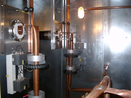 |
This photo shows the interface between feeding cables and antenna tuning unit. To otain the information about the behaviour of each dipole it requires a power measuring facility for indicating the power and a current transformer for determining the phase between the dipoles.
|
|
 |
grounding switch
power measurement and current transformer
|
 |
 |
|
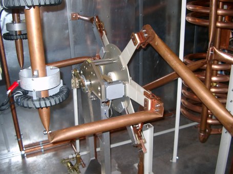
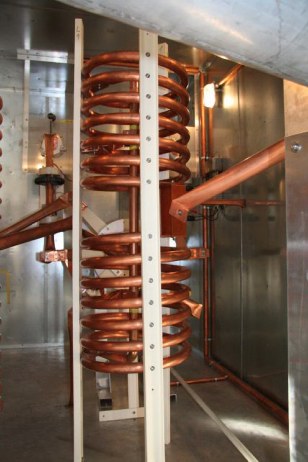
The phase shifting of 90 degrees which is necessary for obtaining the circular polarization of the dipoles is achieved by two coils ( one of the coils L13 on this photo) and one condensor.
|
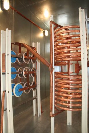
Coil as part of transformation unit from 37,5 ohms to 50 ohms.
|
|
 |
 |
|
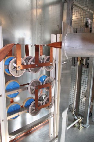
Condensor as part of transformation unit from 37,5 ohms to 50 ohms.
|
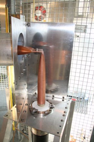
The fixation to the cable which connects the antenna tuning hut with the transmitter.
|
 |
Connecting tube between condensor and cable coming from transmitter.
|
|
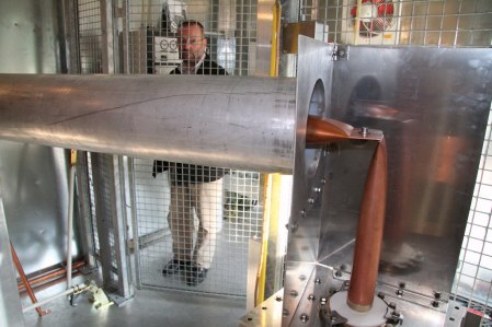 |
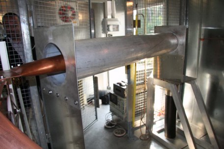
Connecting tube between condensor and cable coming from transmitter.
In the background:
Wolfgang Heßler from T-Systems, head of the transmitter site in Mainflingen
|
previous next
|
Mainflingen cross dipole
|
|
Visitor's statistics:
|
|

now online
|
The flags of the visitors from all over the world
(since 2009-1-18) :
The visitors from the USA and their flags of 50 federal states + DC
(since 2010-3-21):
The visitors from Canada and their flags of 13 provinces & territories
(since 2010-4-24)
|
since 2010-6-27
|
|