Flevoland
|
MW antenna Flevoland - twilight
|
||
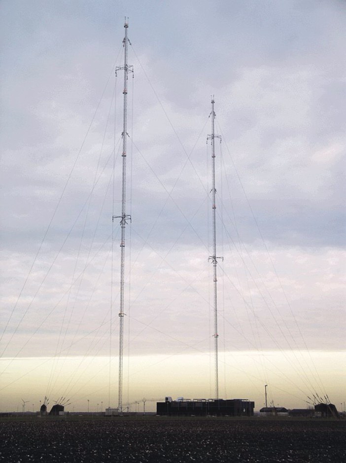 Foto: edwin
|
||
The photo above is taken from http://tips-en-trucs.verdijk.info/zenders/#flevo with the friendly permission of Jan Verdijk.
It demonstrates that it is the best to use twilight for photographing the ropes of an antenna.
|
||
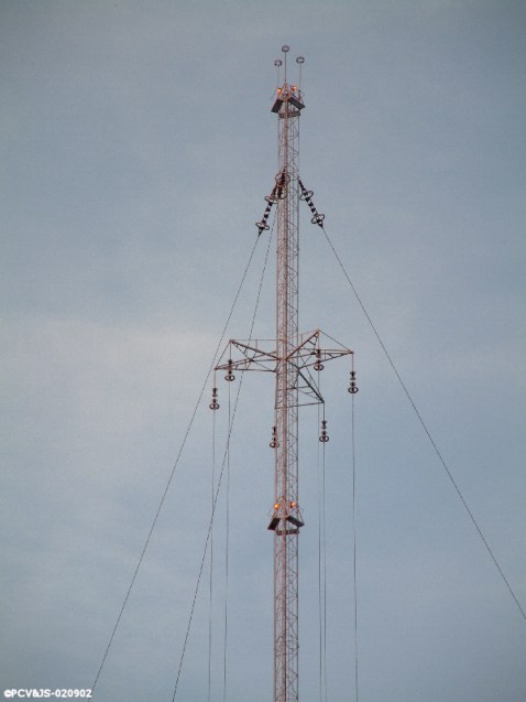 |
The top of one mast
Description of the upper cage
photo taken from
grootnieuwsradio.htm with the friendly permission by Peter Vrakking.
|
 |
The top of one mast
This photo by Tom Jansen shows once more a lot of details.
The spacing between the two guy levels at the top of the mast is 50 m.
|
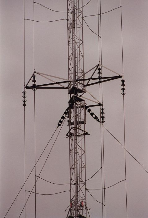 |
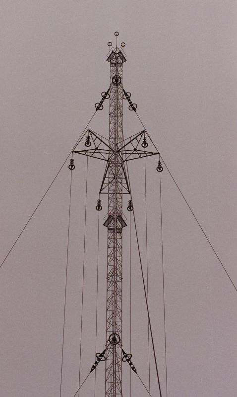
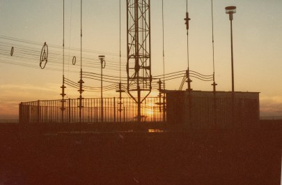
The center of the mast
This photo shows the feeding point of the mast at the height of 90 m.
Here the mast is seperated in two parts by an insulator.
The insulator is installed between the two triangular plates seen in the middle of the photo.
There are two cage ropes, one above and the other below this insulator. The rope cage sonsists of the mast as inner conductor and six vertical ropes as outer conductor.
The horizontal ropes, which can be seen on the photo above and below are short circuits for adjustment of the lengths of the cage ropes.
Description of the upper cage
Description of the lower cage
photo by Tom Jansen
|
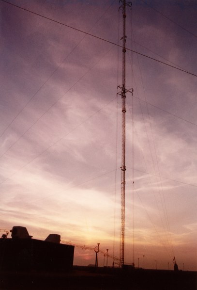 |
Thanks to the twilight many details of the antenna can be recognized on the photos of this page:
1. the vertical ropes of the "cage" around the mast,
2. the cantilevers in the middle of the mast, where this cage is seperated by insulators in an upper and a lower part. This is also the feeding point of the antenna and the upper part of the mast is standing on an insulator at this point.
3. The horizontal ropes between mast and rope cage below the feeding point form a short circuit for a coaxial line formed by the mast as inner conductor and the rope cage as outer conductor (additional explainations on 2E),
4. the guy ropes ( four levels) with insulators only up close to the mast and down at the large base foundation,
5. the coaxial feeder line between mast and transmitter building,
6. the two outlets for the coaxial feeder lines on top of the roof of the transmitter building.
7. Extensions on top of the mast for fine tuning of the length of the antenna.
|
||
 |
Base of the mast
It is shown the open wire coaxial feeder line, the slim foot of the mast, the six vertical ropes of the cage around the mast including the very high voltage insulators, and the horizontal lines connecting the vertical ropes with the tuning elements which are located in the hut.
The fence is a protection for not entering the aeria of very high voltages and currents.
|
||
previous next
|
Flevoland
|
|
Visitor's statistics:
|
|

now online
|
The flags of the visitors from all over the world
(since 2009-1-18) :
The visitors from the USA and their flags of 50 federal states + DC
(since 2010-3-21):
The visitors from Canada and their flags of 13 provinces & territories
(since 2010-4-24)
|
since 2010-6-27
|
|