Mainflingen cross dipole
|
 |
|||
MW Mainflingen cross dipole antenna -
antenna tuning hut and feeding cables
|
Technical description (continued from 2E):
|
|
 |
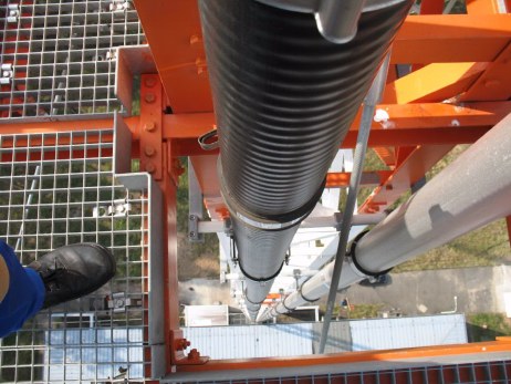
Every dipole is fed via a power cable of 5" (characteristic impedance 75 ohms) which leads vertically from the base of the centre mast (see photo left) to the feeding point of the dipole on top of the mast at the height of appr. 80 m.
A design was to be found in order to allow the tuning of the impedance at feeding point of the dipole. This impedance should correspond as close as possible to characteristic impedance of the cable.
At the same time it was necessary to provide a balun for the symmetrical dipole and the unsymmetrical cable. Both tuning and baluning were realized by a stub (a short circuited line) connected to the feeding point at the dipole and consisting of the feeder cable and a rigid tubular line.
|
|
 |
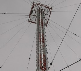 |
Feeder cable and a rigid tubular line are in parallel and fixed to the mast by means of insulators. ( see photo )
The length of the stub allows the transformation of impedance. The stub represents a parallel inductance to the feeding point of the dipole transforming the antenna impedance close to characteristic impedance of the cable (75 ohms).
The dimension of length and width of the dipoles was also carefully chosen in order to obtain an atenna sytem where the dipole impedance is nearly equal to the characteristic impedance of the cable (75 ohms).
|
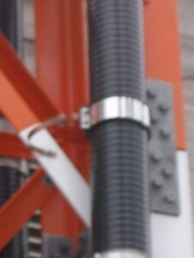
grounding of feeding cable to mast
|
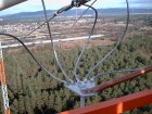
Stub (Carter loop) at the feeding point of dipole consisting of rigid tubular line and feeding cable.
|
|
 |
The stub
The stub consists of the cable and the tube. It is fixed to the mast by means of insulators.
photo: T-Systems
|
|
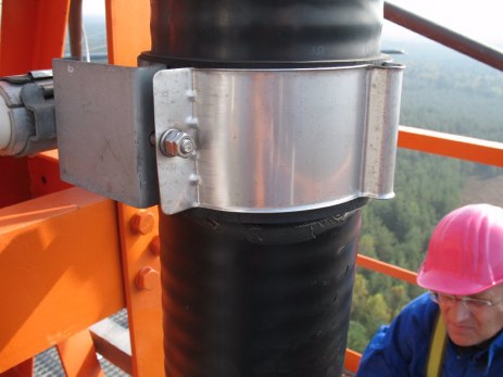 |
The clamp for fastening the cable to the insulator.
Gerhard Baumbach inspecting all details.
photo: T-Systems
|
|
 |
In case the impedance at the feeding point of the dipole corresponds to characteristic impedance of the cable, because the imaginary part of the antenna impedance was tuned nearly to zero, there is nearly no mismatch on the feeding cable.
While the the imaginary part of the dipole impedance was tuned by the stub, the tuning of real part if necessary had to be done by the length of the dipole. It was intended to lower the dipoles for this purpose which luckily was not necessary.
The cable with the seldom characteristic impedance of 75 ohms was chosen because it was much easier to design an antenna system, in particular the shape of the dipoles, with a dipole impedance closer to 75 ohms than to 50 ohms, the usual characteristic impedance of power cables.
|
|
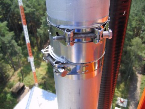
The tubes of the stub are connected by clamps. The length of the tubes is 5 m.
photo: Wolfgang Heßler, T-Systems
|
||
 |
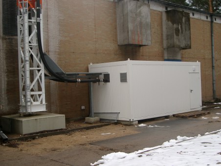
The schematic below shows how balancing, phase shifting and tuning to the output of the transmitter (50 ohms) were realized.
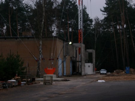
Left: centre mast near to the old transmitting building with container for antenna tuning unit.
In front: foundation for guys of two masts
|
|
 |
||
Drawing showing adaptation of dipole impdance to 50 ohms from right to left:
- dipoles with stub (Carter loop) as balun including tuning to 75 ohms
- feeder cables with characteristic impedance of 75 ohms
- phaseshift of -90° without transformation
- connection of dipoles ( theoretically 37.5 ohms )
- transformation from 37.5 ohms to 50 ohms
|
||
previous next
|
Mainflingen cross dipole
|
|
Visitor's statistics:
|
|

now online
|
The flags of the visitors from all over the world
(since 2009-1-18) :
The visitors from the USA and their flags of 50 federal states + DC
(since 2010-3-21):
The visitors from Canada and their flags of 13 provinces & territories
(since 2010-4-24)
|
since 2010-6-27
|
|